2.7 4-Digital 7-Segment Display
Overview
In this lesson, you will learn about the 4-Digital 7-Segment Display. It consists of four 7-segment displays working together so as to display 4 digit numbers.
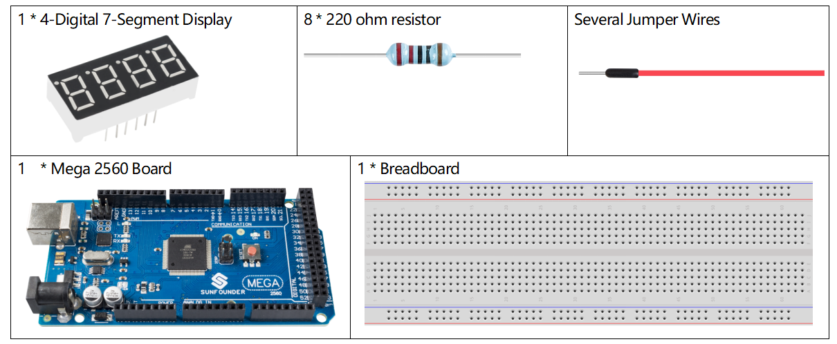
Components Required
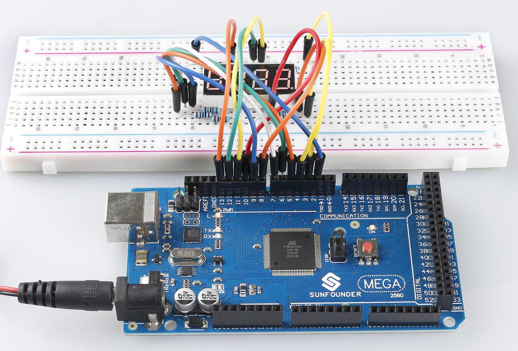
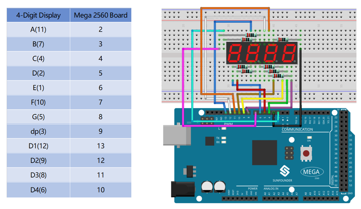
Fritzing Circuit
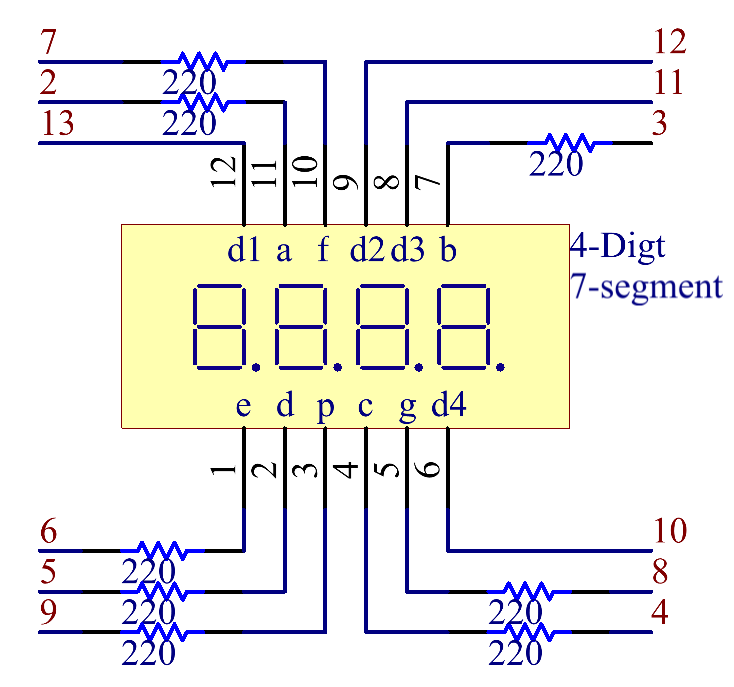
Schematic Diagram
Code
Σημείωση
You can open the file
2.8_ledMatrix.inounder the path ofsunfounder_vincent_kit_for_arduino\code\2.8_ledMatrixdirectly.Or copy this code into Arduino IDE 1/2.
Then Upload the Code to the board.
Please make sure you have added the library called
TimerOne, detailed tutorials refer to Add Libraries.
Code Analysis
There are two points needing your attention:
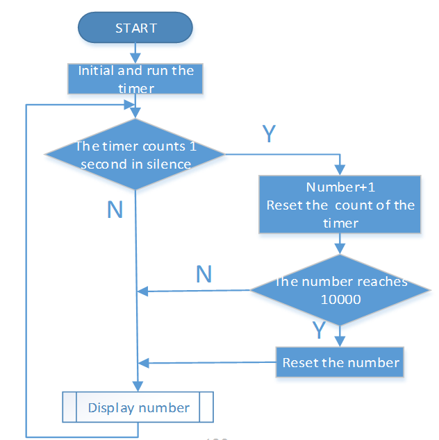
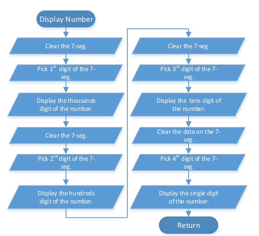
Because every segment display works independently in the 4-Digital 7-Segment Display, the principle of visual persistence is applied to quickly display every 7 segment character in turn to form a continuous character string.
Refer to 2.5 7-Segment Display to check the details of the number display of the 4-Digital 7-Segment Display.
In this example, a library TimerOne.h is used to realize the function of counting.
#include "TimerOne.h"
Library Functions:
void initialize(long microsenconds=1000000)
You must call this method first to use any of the other methods. You can optionally specify the timer’s period here (in microseconds), by default it is set at 1 second.
Σημείωση
This breaks analogWrite() for digital pins 9 and 10 on Arduino.
void attachInterrupt(void (*isr)(), long microseconds=-1);
Calls a function at the specified interval in microseconds. Be careful about trying to execute too complicated of an interrupt at too high of a frequency, or the CPU may never enter the main loop and your program will “lock up”. Note that you can optionally set the period with this function if you include a value in microseconds as the last parameter when you call it.
void detachInterrupte();
Disables the attached interrupt.
Phenomenon Picture